Sail Design: From Measurements to Build Ready Project – Part 2
May 22, 2025
Last issue Part 1 looked at the initial stages of developing a sail. Next time, choosing cloth, finishing the design getting ready to cut panels.
The structural meshing begins and cloth is chosen to be tested for how much load deformation should be expected.
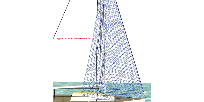
FEA is commonly used in industries where physical testing is impossible or impractical
Finite Element Analysis works by discretizing the domain of interest and then assembling physics equations to solve the engineering problem at hand. By assembling these elements together to represent the physical system, engineers can predict the behavior of the whole structure. With FEA, answering the question, “Will my car be safe after being driven over 100,000 miles?” starts by dividing the car into systems, systems into components, and components into elements using a grid of elements, known as meshing.
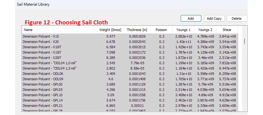
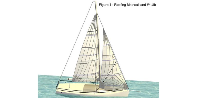
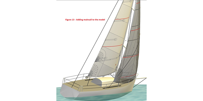
To get a good load map from the aerodynamic pressure and loading information, we really need to include the effect of a mainsail to the results.
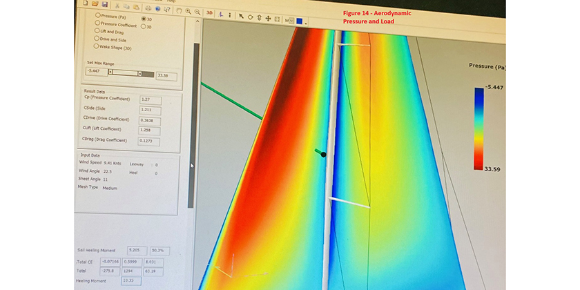
This exercise gives us a deformation chart based on the chosen wind range, sail trim, panel layout and cloth choice. At this point we have more accurate load data and can refine the headstay tension and mast bend amounts. This can go around and around several times until I get a result that meets the needs of the project. What you are optimizing for in this analysis varies from project to project; but customers appreciate when you can keep the cost low, performance high, and meet their expectations of durability.
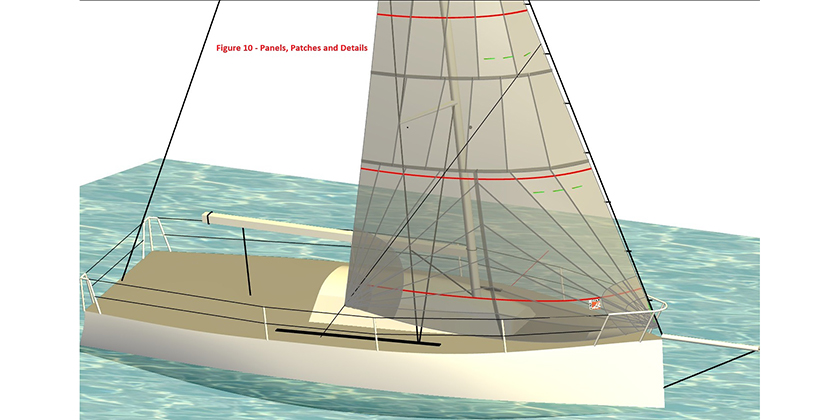
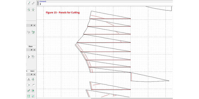
The final part of the sail design is developing the flattened sail panels into a fully marked up cut file for production. After nesting to get the most efficient use of cloth, the file goes to the laser cutting and plotting table. These large cutting tables quickly and very accurately trim out the sail panels to go on to production. The panels are cut and details drawn with repeatability of 100 microns, or about the thickness of a human hair.
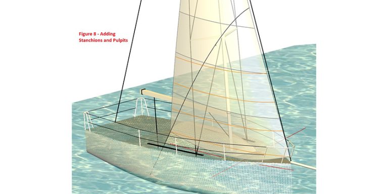
You can see the incremental improvements to the accuracy of the sail design as the 3D model is incorporated into the design. The use of the detailed rig and hull model allowed the sail to be fitted correctly to the boat in sailing condition. This accurate model highlighted the poor fit of the original headsail on the boat. The original sail looked fine at the beginning with the basic 2D layout, but that changed as the sailing model is created.
As you incorporate more data, the computer simulation aids in getting a perfect fit and allows optimizing the sail shape to balance the aerodynamic forces to get more efficient sails.

Keven Piper, two-time Shark 24 World Champion, founded Hamilton, ON-based Bay Sails in 1998. Email: baysails@gmail.com