


Ask Andrew: Will we make it? Fuel gauge troubleshooting
Nov 5, 2020
There’s nothing worse than wondering how much fuel you have on board. You’re left wondering how long you can motor for. As well, you have no idea how much more fuel you can take on at the marina pump. You’re forced to resort to using a combination of dipsticks and jerry cans to compensate for not knowing the tank level.
Many boaters a reluctant to pay a technician to diagnose the fuel gauge, when it’s more of an annoyance – and it doesn’t really prevent the boat from being used.
To complicate the problem, the dash gauge itself is often blamed: ‘I’ll just replace the gauge in the spring. Problem solved’. Easy to assume that this is the case – but the gauge isn’t always the problem’s cause.
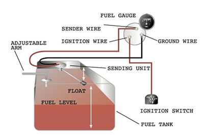 – a complete fuel gauge system
The system is pretty simple – and it’s easy to test and diagnose on your own. Here’s how the system works:
A fuel gauge system is composed of three parts: The gauge itself, the fuel sender, and the wiring between the two.
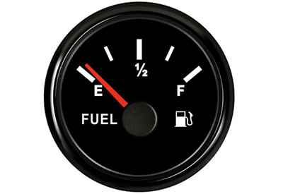
The gauge is dash mounted, and is powered by the ignition circuit. This means that when the key is turned to the ‘accessory’ or ‘on’ positions, the gauge will have power to it.
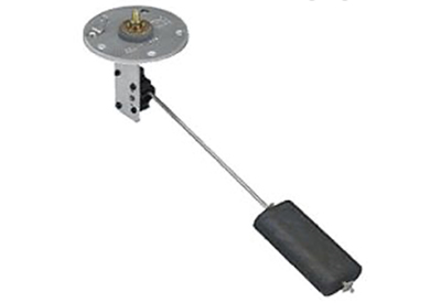
a fuel tank sender
The fuel sender is mounted inside the fuel tank, and is a vertical post with a horizontal arm with a float on the end. The float rises and lowers with the level of the fuel in the tank. The angle between the vertical post and the horizontal float arm uses a rheostat to measured the angle as an electrical resistance. This electrical resistance is transferred to the gauge via a sending wire to the helm, and displayed as a reading on the gauge.
Problems can be diagnosed using a few steps:
1) Ensure that there is power at the gauge: Using a mutimeter (set to the DC voltage scale), measure the voltage at the + (sometimes marked with an ‘I’) and – negative terminals on the back of the gauge, with the key set to the on position. The reading should be the same as the battery voltage. If there is no voltage reading at the gauge, the problem is with the power connection to the gauge itself.
2) Next, test to see if the gauge is reading resistance correctly. This is done in two steps:
a. With power running to the gauge, run a jumper wire between the negative post on the back of the gauge and the sending post (where the sender wire attaches), marked with an ‘S’. When this is done, the gauge should read at it’s lowest setting
b. With power running to the gauge, remove the sender wire from the gauge completely. The gauge should jump to its highest setting. If both of these are true, the gauge is functioning correctly, and the problem lies in either the sending wire, or in the sending unit.
3) Test the sender wire, by removing both ends (from the gauge, and from the sending unit mounted to the top of the fuel tank) and testing for electrical resistance. Set your multimeter to Ohms, and probe each end of the wire. The reading should be as close to zero ohms as possible. If the reading is ‘over limit’ or ‘no continuity’ there is a problem with the sending wire.
4) Next, we test the sending unit. The unit is mounted to the top of the tank using 6 bolts and sealed with a gasket. The unit should be removed and inspected:
a. The float on the end of the arm should be intact and capable of floating
b. The arm should move freely
c. The rheostat should read correctly: when the arm is all the way down, the rheostat should measure near zero ohms. When the arm is at it’s upper (90 degree) position, it should read close to 200 ohms.
d. If any of these are not functioning correctly, the sending unit should be replaced.
5) If the sending unit is to be replaced, note that these units often need to be modified or adjusted to fit your particular tank. Three adjustments need to be made:
a. The vertical arm needs to be fitted to tank depth. Many over-the-counter units come in 24” depths, and are designed to be cut with a hacksaw to the tank depth.
b. The float arm may be overlong, and will need to have the float bent at 90 degrees to compensate for less-wide tanks
c. The rheostat may need to be adjusted per manufacturer recommendations to read ‘empty’ and ‘full’ accurately.
As you can see, the system is fairly simple, and straightforward to diagnose accurately. Most chandleries will have fuel gauges and senders available, once the problem is determined.
 Andrew McDonald is the owner of Lakeside Marine Services – a boat repair/maintenance firm based in Toronto. Andrew has worked in the marine industry for 12 years and is a graduate of the Georgian College ‘Mechanical Techniques – Marine Engine Mechanic’ program.