Ask Andrew: NMEA 2000 Set-up – Part 2
Nov 24, 2022
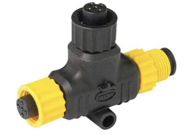
a close-up view of a t-connector
Last issue we explored NMEA 2000 networking, including the advantages of creating an on-board network, and what that network is capable of. This week, we’ll get more in depth with how to design, set-up and install an NMEA 2000 network.
NMEA 2000 is the standard networking system to allow instruments from multiple manufacturers to work and communicate together:
• older instruments to marry up and communicate across manufacturers. A five-year-old Lowrance depth transducer can still communicate with a brand new Garmin MFD(multi-function display).
• Upgrades and expansions become simple: A secondary display can be added for convenience. A new trolling motor can be added and networked so that the forward-scan capabilities of the trolling motor can be seen along side the depth and temperature information from a transom-mounted transducer.
• An autopilot system can be linked with a chartplotter, in turn linked to a VHF radio AIS system linked to forward scanning VR cameras, forward and side-scan transducers and GPS information. This allows a boat to (almost) update it’s own course and drive itself. (Spoiler Alert: This is where these capabilities are heading).
• Older helm gauges can be replaced by including an outboard engine into the network, allowing engine data to be displayed on an MFD alongside chart and scanning data.
The applications are endless, and can be tailored to your own comfort level, budget and the way that you enjoy boating.
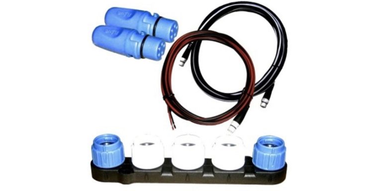
 a series of t-connectors creating a backbone, with terminal ends correctly in place. The yellow drop cable is for 12V DC power, and the black and grey drops cables connect devices to the network.
So how to you actually implement an NMEA 2000 network? Maybe you’re looking to replace your Multi-Function Display. Perhaps you want to replace an older transducer. Maybe you’re adding a trolling motor, GPS puck, or second forward-scanning transducer.
Here’s how it all works:
Imagine you have a simple MFD and depth transducer set-up. The MFD will have a receptacle labeled ‘transducer’: the transducer cord runs to the back of the MFD and plugs in. Pretty simple. As soon as you want to add more inputs, you run out of space. This is where the network comes into play.
The NMEA 2000 system is meant to be a plug-and-play system. Each item in the network runs down a ‘drop cable’ to a ‘t-connector’ to a network ‘Backbone’. The backbone runs lengthwise and allows drop cables to branch of it at any required locations at stern, helm and bow.
An NMEA starter kit is a great place to start. This will include a backbone cable (one long cable designed to run lengthwise along the vessel), t-connectors (allowing cables to branch off from the backbone), drop-cables (running from the t-connectors to each device on the network), a power cable (running from a t-connector to power (fuse panel, or battery), and terminal caps (which tell the signal where the end of the connections are).
 a planning diagram of the NMEA network, clearly showing each of the components.
I tend to start with a diagram. It’s a line with branches off of it, showing the backbone, Ts, and any/all networked devices.
Next, I locate the best location for the power connection (into a fuse panel, or directly to the battery). NMEA 2000 power cables have fuses included. I then determine the cable routing for the backbone, where T-connectors will be added, and I measure approximate distances between appliances and the backbone. Drop cables can be up to 20ft from the backbone, and the backbone and t-connectors can be ‘daisy-chained’ to allow larger lengths or combinations to be added in unlimited ways: multiple t-connectors can be stacked on each other, and multiple backbone cable lengths can be added end-to-end. The power source can be at the end or middle of the network connections, depending on the voltage drop along the network. 3.0V DC is the threshold along the entire network length. If this threshold is exceeded with the power source at an end point, the power cable should be moved to a mid-point in the network (with voltage drop balanced across the network). If 3.0V DC voltage drop is exceeded with the power source in the middle of the network, a professional installer should be contacted in order to find problems and solutions.
Next, I determine proper termination: the network has to have an endpoint, where the daisy-chain ends at the last t-connector to the fore and aft-most appliance. Without the terminal caps in place correctly, the network won’t work.
Next: connect the appropriate length backbone cables to t-connectors. Run drop cables to appliances. Confirm that all connections mate with each other. Add/change dongles as required to marry up standard with micro connectors, and with manufacturer-specific ends with NMEA 2000 ends.
Once all is connected, power up the network and test at the Multi-function display. Confirm that the settings in the MFD are set to read each networked device.
A few further considerations:
1) There should be only one power source to any network. Never add a secondary power cable.
2) The distance between any two points on the network should not exceed 100m (328ft)
3) The maximum length of all drop cables should not exceed 78m (256ft)
4) The maximum length of a single drop cable to an NMEA 2000 device is 6m (20 ft)
5) No more than 50 NMEA 2000 devices can be connected to a network.
For most of us, these thresholds are well within our on-board networking needs.
NMEA 2000 is meant to be DIY and plug-and-play. Its purpose is to simplify on-board networking, across brands and manufacturers.
DIY or Professional? Reading this info and gaining familiarity the system is worthwhile for any boater so that you understand the inner workings of your boat. But if you’re having trouble setting up your onboard network or simply prefer the reassurance of having a marine expert undertake the work, consult a marine tech who is familiar (and/or certified) in NMEA 2000 network installations.
 Andrew McDonald is the owner of Lakeside Marine Services – a boat repair/maintenance firm based in Toronto. Andrew has worked in the marine industry for 12 years and is a graduate of the Georgian College ‘Mechanical Techniques – Marine Engine Mechanic’ program.