Perfect Prop for your Purpose
By Rob Macleod
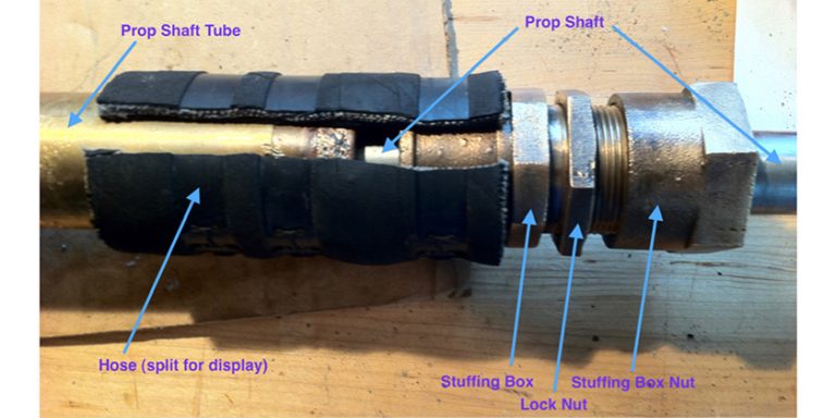
This article is the first of 2 parts. Part 1 deals propellers for displacement boats and Part 2 will cover the rest of the drive train (i.e. coupling, shaft, stuffing box, stern tube and cutlass bearing) and a comparison of fixed, folding and feathering propellers for sailboats.
Deciding to change the propeller on your boat is not a binary decision, like “Do I want a red one or a blue one.” The science of propeller design dates back to Archimedes (287-212 B.C.). Selecting and fitting a boat propeller is often referred to as a black art, because the terminolgy and mechanics of props seems as much art as it is science. Don’t let the term fool you. Prop professionals have the charts, formulae and algorithms to back up their recommendations.
Selection of the proper prop for your purpose is based on what you want or need to achieve: greater fuel economy, faster cruising speed, smoother operation or faster on to a plane. In his 6th rule of thumb, Dave Gerr states, “The same propeller can’t deliver both high speed and maximum power …
A propeller sized for high speed has a small diameter and maximum pitch. A propeller sized for power or thrust has a large diameter.”
Propeller Handbook: The Complete Reference for Choosing, Installing, and Understanding Boat Propellers
We are here to explore is exactly what does he means by that.
 Props – What and Why
To de-mystify the black art you first have to learn the language. Underlined words are defined in this article. I have purposely left out the more basic terms.
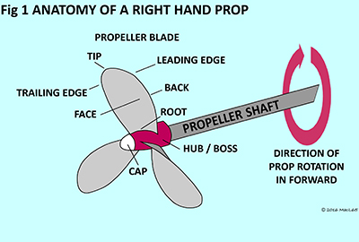
Hub (or boss) – the centre section of the propeller, necessary to hold the blades in place
Hub (or boss) – the centre section of the propeller, necessary to hold the blades in place
Blade face and back – the face is the side of the blade looking forward from the stern, the back is the side of each blade looking aft.
Blade root and tip – the root is the part of the blade closest to the propeller hub and the tip is furthest
Leading and trailing edges – The leading edge is the part of the blade that first makes contact with the water as the propeller rotates. The trailing edge is the part the blade that makes contact with the water last as the propeller rotates.
Rotation – props rotate to the right – right hand (RH) or left – left hand (LH). Right hand means the propeller turns clockwise (to the right at the top) when viewed from astern. The majority of single engine boats have right hand props. Twin engine boats usually have the starboard engine as the right hand and the port engine as the left hand, so the water is being pulled from the centreline and not forced into the center.
Some single engine boats (like my 1981 CS36T) have a v-drive after the transmission. This installation is dictated by a very tight engine room where the engine had to be installed backwards and the v-drive re-aligns the prop shaft in the proper direction to save space.
 Prop walk – prop walk is the tendency of a boat to move sideways as the result of prop rotation in reverse. Although very slight in forward, the sideways movement can be quite pronounced in reverse, especially when starting from a full stop, such as when backing out of your slip. The primary cause of prop walk is the difference in density of water between the top of the prop and the bottom. With denser water further down, there is more power developed at the bottom of the prop than at the top. So a right hand (RH) prop in reverse (turning counter-clockwise) will pull the stern of the boat to port. LH props pull to starboard and twin engined boats, properly set up, should cancel out any prop walk.
DAR – Disc area ratio (also referred to as BAR – Blade Area Ratio) defines the ratio of surface area of the blades divided by the overall surface area defined by the circumference of the propellor
Relation of DAR to drag – if DAR increases then drag (defined below) increases.
Diameter, pitch, slip and thrust – Now we are getting to what really moves the boat. The diameter is measured across the widest part of the prop. On an even-numbered blade prop (i.e. 2 or 4) the diameter is measured is from tip to tip, through the centre of the hub. On an odd-numbered blade prop (i.e. 3 or 5) it is easier to measure from the centre of the hub to one of the tips (the radius) and then double the number to determine the diameter. The diameter of the blade in any application is limited by the aperture – the space available for a propeller.
 Pitch is the theoretical distance a propeller will travel forward in one revolution of the propeller. Theoretically a propeller with an 18” pitch travels forward 1-1/2 feet (18”) with each rotation of the propeller. Slip is the difference between the theoretical distance and the actual distance the propeller travels caused by inefficiencies in prop and anomalies (i.e. bubbles / disturbance) in the water. A properly matched propeller will move forward about 80 to 90 perfect of the theoretical pitch.
Cup – There is a slight curl or concave characteristic of each propeller blade’s face. As propellers take on more aerodynamic shapes, the cup of the propeller can be used to increase lift and reduce cavitation.
Lift and drag – Lift is the force generated by the propeller’s blades in a manner similar to a sail or an aircraft wing. To understand lift as it relates to propellers, look at what happens to a stream of water as it makes contact with the curved surface of a spoon.
Notice, as the stream contacts the back of the spoon (propeller blade) the stream clings to the surface. The stream continues along the surface – deflecting towards the face. According to Newton’s 3rd law of physics, for every action there is an opposite and equal reaction. In this case, the water moves aft and the propeller blade generates lift forward. Drag is the resistance as the stream comes in contact with the blade. As long as the lift significantly exceeds drag, lift will move the boat forward.
 The proper pitch of the propeller blade results in smooth flow over the blade. Maintaining flow contact across the width of the blade reduces cavitation.
Cavitation and ventilation – cavitation occurs when the flow of water over the prop starts to bubble in the partial vacuum caused by: a damaged prop, excessive propeller speed, excessive loading or an incorrectly sized propeller.
Cavitation bubbles are actually vapour, created when the flow of water over the blade starts to boil as the result of the low pressure. The bubbles collapse (implode) when they reach an area of higher pressure. This bubble break down can happen with such force that the bubbles actually pull metal off the surface of the blade causing erosion or a “cavitation burn”. Fig 7 shows how water can actually boil at room temperature, if the pressure on the back of the blade is low enough.
Ventilation takes place when a propeller operates too close to the water surface. Surface air or exhaust gases are drawn into the propeller blade due to the localized low pressure around propeller. In effect, the prop “digs a hole” in the water. Ventilation is an issue because it can lead to excessive slippage. Excess slippage can cause cavitation.
Gear reduction – The reduction gear reduces the speed at which the propeller shaft and propeller turn. Engine speeds in the range of 2500 to 3000 rpm are significantly faster than a larger propeller can be efficiently turned. Slowing the revolutions of the shaft at a given engine rpm means more power is available to turn the propeller – essential for displacement boats.
How many blades?
 That is the big question.
 A 2-blade prop is effective in most calm water situations. It is not recommended for extensive coastal cruising and definitely not for blue water. All of the prop experts I talked with said to install at least a 3-blade for a coastal trip (i.e. from the Great Lakes to the Bahamas or Vancouver to Mexico). The challenge on a sailboat is, if you install a fixed 3-blade, the drag will be equivalent to towing a water bucket. Installing a fixed 4-blade on a sailing boat is equivalent to towing 2 water buckets. There are detailed charts and graphs to explain all this, but my math-resistant brain understands 1 and 2 buckets.
Propeller Calculation
When you approach your propellor professional, you will be asked for the following information, so you might as well start chasing it down now. Some of it will be easy to get. For older boats, you may want to start looking for the manufacturers information plates on you engine and transmission.
Data includes:
Ship data: manufacturer, model, year of construction, LOA, LWL, beam, draught, displacement, loaded cruising weight, max speed at max rpm, cruising speed at (what) rpm.
Engine data: # of engines, manufacturer, model, max rpm, HP or Kw, type of gearbox, reduction ratio, shaft diameter, Society of Automotive Engineer or SAE (Y or N)
 [Note: The reason for this is so propellers with different hub lengths (i.e. different diameters at the large end of the taper) will fit the standard shaft diameter and have the nut face in the proper position on the shaft.]
 For example, some propellors require a tapered shaft. The original Gori folding prop on my CS36 required the shaft be shortened and tapered. A new VariProfile feathering prop comes with an adapter that fits over the threads of standard prop shaft, allowing you to carry your present propeller as backup.
Present propeller: Diameter and pitch, RH or LH, fixed, folding or feathering, # blades, type of boat (sail, motorboat, trawler, etc.), hull type (displacement, semi-displacement, planing) and chine (round or hard)
Summary
Now that you can speak the language, gather your information and go talk to 2, 3 or even 4 propellor vendors. Ask questions. Ask for specifics on your boat. If you do your homework, you will help your professional help you get the Perfect Prop for your Purpose – speed, power or the right balance of the two.
In Part 2 when we look at the rest of the propeller system and the 3-Fs in props for sailboats – fixed, folding and feathering.