Boat nerd: Boat DC Electrics – part 3
Feb 10, 2022
(For Parts 1 and 2 head to our Jan 13 and 27 CYOB digests – click Archives above)
Voltage Drop
The other factor that affects wire size after the “how much current can it handle before burning up” question is, what is the voltage drop across the wire? At 120V if we lose a volt or two along the wire run it’s no big deal. At 12V if we lose a volt or two it’s a very different story. The results of voltage loss can be:
• throwing away a portion of your battery capacity for no good reason (going to heat in the wire) making the system less efficient and discharging faster
• motors may run slower or overheat
• electronics may be on the verge of resetting
• fringes will run less efficiently or shutdown on low voltage
• As voltage at the end device drops for a constant Watt load, current increases
• In systems with inverters (talked about later) the resultant higher currents can lead to an overload condition. The lower voltage can also trigger an undervoltage alarm/cutoff.
• Voltage drop during charging can lead to undercharging or extended charging times
In selecting a bigger wire with a larger cross section , yes the rated ampaicty goes up and may be way more than you need but the voltage drop across the cable comes down which is a good thing. Voltage drop is specified in % and the usual thresholds are 3% for critical functions which affect the safe operation of the vessel(running lights, bilge blowers, electronics and distribution supply circuits) and 10% for less critical functions (cabin lighting, bait pumps). 3% works out to 0.36V drop at 12V or 0.72 at 24V, while 10% works out to 1.2V drop at 12V.
This one of the advantages to going to a higher battery voltage.
Wire Sizing
There are tables (see figure 4 above as an example) and applications available on the Internet that help with wire sizing. I can recommend Blue Sea Systems (Bluessea.com) for an application called “Circuit Wizard” you can download, enter all your parameters and hit “calculate”. For IOS devices there is also an app called Wiresizer.
ABYC standards state #16 is the minimum wire size that should be used for running circuits for robustness.
An interesting point when looking at wire sizing for high current devices, is that according to ABYC standards you cannot double up or parallel cables to increase current capacity. If you need 500A you cannot parallel two cables rated for 250A. Paralleled cables can only be used to lower voltage drop and the over current protection is designed based on the ampacity of one cable alone. This allows for one of the cables to become accidentally disconnected without creating a hazardous condition.
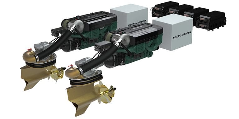
If the vessel has many high load devices such as 3KVA or higher inverter, electric winches and windlass, and thrusters that would result in long runs of very heavy cable or border on not possible, increasing the house bank voltage my help. Going to 24V would half the current drawn by the devices and result in smaller, lighter, less expensive cabling. A 24VDC-12VDC converter would be used to power legacy 12V devices such as VHF radios. While perhaps not applicable to a 30’ vessel, when the vessel size gets over 40’ the weight savings may become substantial.
Wire Sizing example – you are looking to add a new chart plotter in the cockpit, 10’ from the nearest distribution panel. What wire size do I need?
It is a 10’ run from the panel to the plotter and 10’ back, for a 20’ round trip cable distance. We are looking at 3% voltage drop max(chart plotter is classed as critical function), the cable will not pass through the engine room, it is not bundled with any other cabling, the plotter draws 7 Amps, we are using 105C wire, and we will have it turned on for a minimum of 3 hours (load duration).
Entering the values in the app, the answer is #12 gauge wire. Even though #18 can handle the current, for voltage drop reasons we must upsize the cable.

Figure 5
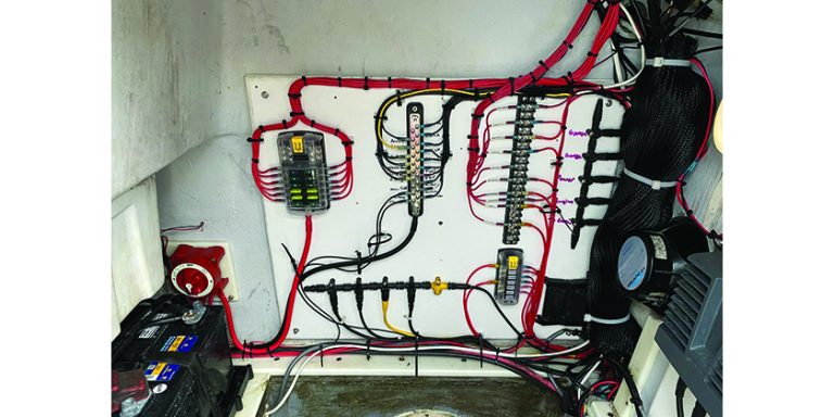
Wire insulation is available in different colours and there is a general agreement of what colours are used for what function. For example red is for +12 supply, yellow is for 12V negative (this used to be black, however in North American black is also 120V hot so to not confuse the two yellow is now used for negative). A more complete table is shown in figure 5. Using different coloured wiring also helps in tracing and trouble shooting problems.
Labelling both ends of a wire with a number or function (often under clear heatshrink) will also help immeasurably in the future when you have an issue troubleshoot.
Wire terminations
Having run our wire how do we connect or terminate it?
“Well made electrical connections are essential for the performance and safety of a boat’s electrical system and even the best system design can be compromised by a faulty connection.”
Often a wire is meant to attach to a threaded post under a washer and nut or under a screw on a terminal block. In marine wiring we do not just wrap the wire clockwise around the terminal and tighten as this would be subject to corrosion and working free. The standard way to terminate a wire is to crimp a suitable lug onto the wire. A ring terminal would be the normal device used as even if the screw or nut were to loosen the wire would not come adrift. Spade lugs might also be used but get the type with the small 90 degree upturn at the end of the fingers. If the screw or nut loosens a standard spade lug could come totally away from the terminal, hover a captive spade lug with the upturned forks would stay in place.
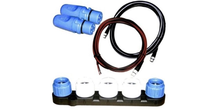
There are also push on and bullet terminals to facilitate connections to devices that may need to be removed in the future such as light fixtures. There are also barrel or butt splices meant to join two wires together. See figure 6 below for example of lugs and terminals.
Terminals typically come with no, PVC, Nylon or heatshrink barrel (the crimp part) covering. For marine use heatshrink terminals are the best (and most expensive!) followed by terminals with nylon barrels.
The terminal barrels are colour coded for wire size. Pink/red is meant for #22-18AWG wiring, blue for #16-14 AWG, and yellow for #12-10 AWG.
If you need to join two wires in different size brackets, i.e. a #14 wire to a #18 wire, there are also step down butt splices.
Heatshrink terminals with their hot melt glue have the advantage of totaling sealing the terminal and wire against water intrusion and are almost a must for use in a salt water environment. (Or use a piece of heatshrink over a regular terminal) On our boat down south the bow nav light was wired with several sets of standard butt splices, no heatshrink. The light worked for the first few years, became intermittent (with the standard question of wtf is going on), and finally stopped working. The salt air had rotted the wires in the butt splices
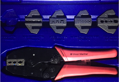
To install these crimp on terminals use a quality ratchet crimper. See figure 7

Figure 6
Figure 7
Once you get to #8 cables and larger, you are pretty much into individual crimp lugs. These lugs should be of the closed barrel end variety so no water can get into the wire via the lug (see the right most lug in figure 6). When combined with hot melt glue heatshrink over the wire and back of the lug you should have a water tight termination. If water does get into the end of your wire it will wick up the wire for a considerable distance and start corroding away the wire.
Special crimpers are needed for these lugs that crimp the entire circumference, although if you only have one or two terminals to install Anchor makes an inexpensive hammer crimper. For more information there is an article at “Marine how to” (marinehowto.com), detailing how to make battery cables.
ABYC also has online learning courses (at a cost) that cover among other things, making good, long-lasting electrical connections. Their WIRING TERMINATIONS, takes a close look at the fundamentals of wire selection, terminal types, necessary tools, and general installation best practices.
Preview:
Full course:
https://abyc.elevate.commpartners.com/products/wiring-terminations
The topic of soldering wires comes up from time to time. I would not solder wires above #18 gauge. Soldering turns our flexible wire into a rigid one at the solder joint. ABYC standards call for any soldered connection to not be the sole mechanical connection. I will use soldered connections (think digital data wiring) on very small wires where I first connect the two wires with a Western Union splice for mechanical strength, solder it, cover with hot melt glue heat shrink, and support it to limit wire movement.
Next time: Bolted connections and overcurrent protection

CYOB’s Boat Nerd, Mike Wheatstone, has enjoyed sailing since he was in his mid teens. A Queen’s electrical engineer by training, he spent his career working for Ontario Hydro and Hydro One. There he worked in engineering supporting the power system control centres.
His first boat in 1980 was a Shark. With a growing family’s 2-foot-itis, there were upgrades to a Grampian 26, CS34 and currently a Hunter36. Now retired, Mike and his family spend summers on the Hunter (Dragonfyre) and winters in the Caribbean on their Leopard 43 cat (Peregrine).