Perfect Prop for your Purpose – Part 2
by Rob MacLeod
A propeller is only as effective as the rest of the drive system. This is a bold statement; but the two experts I talked with while researching this article agree. Robert Huber of Wiggers Marine in Bowmanville, ON and Jamie Fuderer of Kawartha Prop Repair in Buckhorn, ON confirmed that, although it is critical to have the right size, pitch and type of propeller for your boat to gain maximum power from your marine engine, there are a number of inhibitors in the rest of the system that can rob your engine and prop of their ability to propel your boat at maximum speed.
Those other parts of the system include the motor mounts, coupling, stuffing box, shaft log, strut (sometimes referred to as a P-bracket) and the cutlass bearing. In addition, if the sacrificial anode attached to the propeller shaft is installed too close forward of the cutlass bearing it can restrict the flow of water over the bearing resulting in increased friction, loss of power and pre-mature failure of the cutlass bearing. Water is the lubricant for the cutlass bearing.
Let’s define each of the drive train components and some of their variables. For the sake of this article, we are assuming the engine and transmission are operating at peak efficiency.
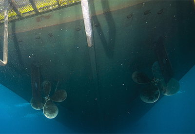
 The Marine Drive System
In an excellent article on Drive System Alignement in YachtSurvey.com (http://www.yachtsurvey.com/Alignment2.htm), David Pascoe explains that although the connection of the shaft coupling to the transmission coupling can be aligned to within a few thousands of an inch, the rest of the system “is essentially a free-floating, semi-self-aligning system”. How does he explain that? Rubber. Starting with the rubber in the engine mounts the propeller shaft floats – and flexes – on a combination of flexible mounts through the stuffing box, the shaft log and the cutlass bearing in the strut.
Engine (motor) mounts – play the vital role of holding the engine off the hull of the boat, absorbing vibration from the engine and having the capacity to adjust the engine alignment relative to the propeller shaft. Absorbing engine vibration not only makes the ride of the boat more enjoyable, it also prevents the vibrations from wearing away at the other components, especially the stuffing box, shaft log bearing and the cutlass bearing.
 Engine mounts can lose their ability to absorb vibration if they are damaged. In Figure 2, the motor mount was damaged when a line fowled the prop. The bend in the bolt is obvious. Not so obvious, unless closely inspected, is the deteriorated rubber isolation. This breakdown can be caused by oil leaking onto the mount, sea water and time. All four motor mounts should be inspected each season and replaced at the first sign of damage or fatigue.
Coupling – The coupling is used to connect the output shaft of the transmission to the propeller shaft. For the most part, this is a metal on metal connection and can be aligned to within a thousandth of an inch (.001 in. or .025 mm) as per American Boat and Yacht Council (ABYC) standard
There are two basic types of misalignment of the shaft – offset and angular. Offset misalignment occurs when the centre of the prop shaft is not centred on the centre of the transmission coupling. The sign of this is the gap where the couplings meet shows the face of one of the couplings.
The second type of misalignment is angular and occurs when the coupling faces have a gap that is larger on one side of the coupling connection than the opposite side.
 The alignment reading is taken by a feeler gauge at opposite sides of the coupling. To complete the measurement, loosen the nuts holding the shaft coupling to the transmission coupling. Insert the blade of the feeler gauge in the gap between the two couplings, changing to thicker or thinner blades until a slight resistance is felt. Note the thickness of the blade. Repeat the process on the opposite side (1800) of the coupling connection. Calculate the difference between the 2 blades. For example, if the gap on the port side measures .011 inches and the starboard side measures 0.21 in – that is a .010 in (or 10-thousands of an inch) difference, and that is far too much. Next, rotate the shaft 90 degress and repeat the same 2-reading process.
 The process for aligning the engine to eliminate the large gap is beyond the scope of the article.
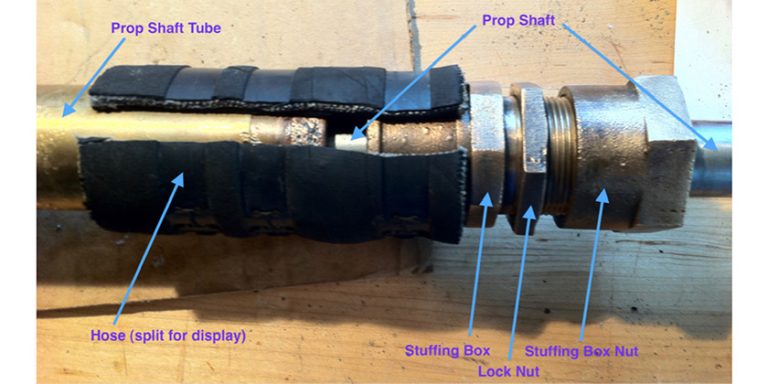
Shaft log and Shaft Seal – The shaft log allows the shaft to exit the hull and helps align the shaft to the transmission. Some shaft logs are metal (many power boats) and can be replaced when necessary while others are molded into the hull of the boat – common on production sailboats.
The shaft seal is an integral part of the shaft log and prevents the water from entering the boat through the shaft log. Various types of shaft seals can be used – packing gland (Figure 6) or dripless – such as PSS® and Lasdrop® .The packing-type gland can be  repacked while the shaft is in the boat. The seal-type requires that the shaft be removed to replace the rubber Neoprene seal unless a second (spare) seal is installed on the shaft while the shaft is out of the boat.
Strut and Cutlass Bearing –The strut is designed to allow the smoothest flow of water over its surface to minimize drag and to align the prop shaft through the shaftlog to the transmission coupling. The shaft is mounted in a flexible rubber casing – the cutlass bearing.
 A cutlass bearing is a metal tube, slightly larger in diameter than the prop shaft and with rubber strips that cushion the shaft. Spaces between the strips allow water to flow through to lubricate the cutlass bearing.
Anode – A poorly installed anode can substantially shorten the life and effectiveness of the cutlass bearing. Used to protect the metal parts of the boat from electrolysis, if installed too close to the bearing and forward of the strut, the anode can reduce the flow of water to and through the bearing. Most effective installation is 2 – 3 inches forward of the cutlass bearing.
Propeller Options for Sailboats
That brings us right back to where Part 1 of this article left off – the propeller itself. So far we have only looked at fixed propellers for both power and sail boats. When a boat is under power the propeller options are pretty much the same – size and pitch and number of blades.
 When a sailor turns off the engine and starts the sail, the propeller changes from being an asset to being a potential liability. Once you eliminate the thrust of a propeller, all you have left is drag. That leads us to the three primary choices of propellors for a sailboat – fixed, folding and feathering (or variable pitch).
Fixed Propellers – For general purpose sailboats, a fixed two-blade propeller is the best trade off. It will move a boat through the water at the rated rpms and will produce the least drag of any fixed blade prop. If one of the blades can be positioned vertically while sailing, then drag from the prop is minimized as the top blade can ‘hide’ in the wake of the keel and strut.
Three- and four-blade props add more power when motoring and increased drag when sailing. The resultant drag has been described as equivilant to dragging a bucket (three-blade) and two buckets (four-blade).
Folding Propellers – since the late 70s and early 80s, sailboat propellers have been designed to fold. Anytime a couple of sailors discuss folding props, there is undoubetedly a story about how the prop didn’t open properly or only one blade deployed.
Three decades of engineering have significantly improved the funtioning of today’s folding props and for racing sailors, they remain a very viable method of reducing drag while sailing. Compare the shape of the blades in the 80’s era folding prop (top) with those of the more recent Volvo folding prop (bottom).
 Feathering Propellers (or Variable Pitch Propellers) – Propellers that can alter their pitch while underway provide a significant improvement in both power and drag. In addition, the efficiencies improve engine performance by allowing the engine to run at its rated RPMs. In turn, this ensures the fuel to burn more efficiently and the engine works at its designed operating temperature. Matching the pitch of the propeller with the revolutions of the prop shaft increases power and efficiency, then – when feathering – presents a significantly reduced profile while under sail – greatly reducing drag. Several variable pitch prop makers – Vari-prop (represented by Nautilus Propeller of Toronto and Max Prop distributed by Paynes Marine Group.
For an excellent article on the care and maintence of feathering and folding props, refer to CY DIY and How-to (https://canadianboating.ca/diy/maintenance/711-folding-and-feathering-props)
 In conclusion, think of your prop as part of a system – engine, transmission, and the drive train covered here. If one part of the system is weak, the entire system will be inefficient.
See you on the water. Rob MacLeod